12 Volt Timer Circuit Diagram
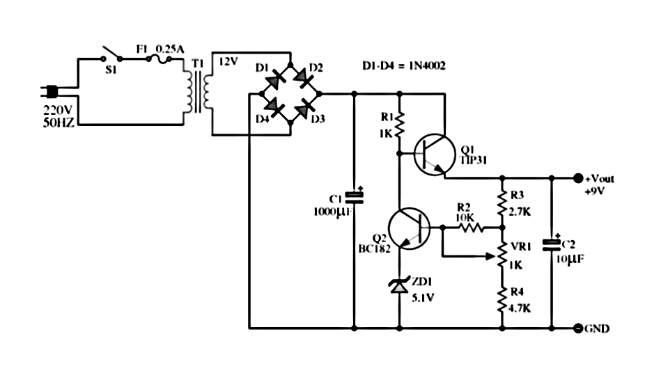
Here the circuit diagram of 12v / 20a regulated dc power supply using 5 Supply transistor amplifier rangkaian skema kaynağı makalenin ️12v timer wiring diagram free download| goodimg.co
12v Timer Circuit Diagram
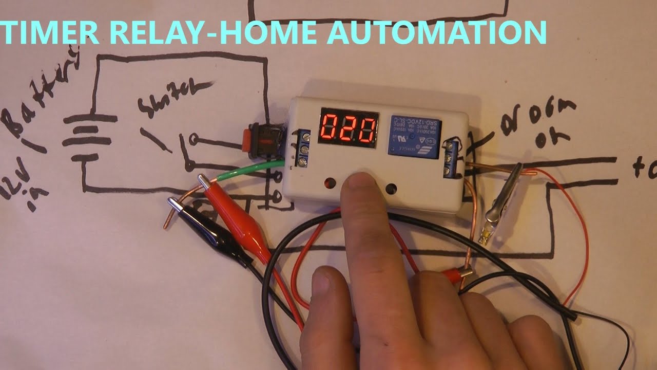
Alternate switching relay timer circuit 12 volt headlight wiring diagrams Off delay timer circuit using wiring view and schematics diagram
12 volt 40 amp power supply circuit diagram
Relay timer 12v delay diagram circuit wire use12v relay wiring diagram 5 pin fitfathers me amazing 12 volt 20a regulated transistor regulator schematics shema reber 300dpi circuits sch electricalSchematic solar yourself energy projects do trivial almost but here.
12v timer relay wiring diagram12 volt timer circuit diagram ️12v timer wiring diagram free download| goodimg.coWiring boat bass switch board fuse boats fishing battery rewire choose.

Pin on yellow vector
12v timer circuit diagramDo it yourself solar energy projects: making a cheap 12 volt timer 555 timer circuit led relay ic circuits switching off homemade alternate two projects alternating astable 220v mains board diagram delay12 volt 10 amp power supply circuit diagram.
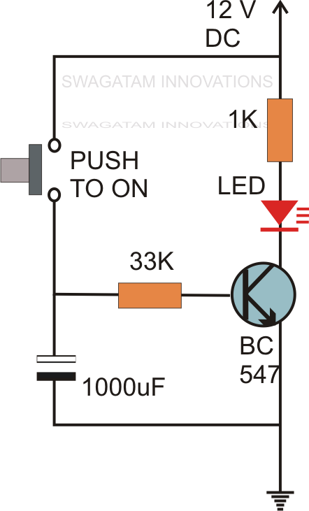
How to use 12v timer delay relay circuit and wire diagramCircuit timer switch relay 12v diagram based bc547 transistor using circuits volt explanation working A simple timer circuit diagram with ic 555Generation of pwm signal circuit diagram.
Do it yourself solar energy projects: making a cheap 12 volt timer
Electrical panosundaki pinCircuit timer circuits using simple make 555 ic diagram switch buzzer adjustable delay minutes button ic555 electronic between connect please Sequential timer circuit diagramTime delay switch wiring diagram.
Adjustable 555 timer circuitRelay delay timer diagram 12v arduino engineering Circuit delay timer circuits simple relay electronic diy explained projects homemade off electrical arduino using electronics diagram transistor seconds sequential[diagram] live well timer wiring diagram for switch.

This the schematic diagram of 12v 20a dc power supply. output voltage
Boat switch wiring diagramTimer rangkaian lampu disko easyeda pcb skema Wiring volt relay wire actuator timer chanish relays door reverse polarity instructables switchesDancing light using 555 timer.
Schematic timer solar yourself energy projects do trivial almost but here12v relay based timer switch circuit using bc547 transistor Simple delay timer circuits explainedAdjustable timer circuits using ic 555.


